
Ranter

Join devRant
Do all the things like
++ or -- rants, post your own rants, comment on others' rants and build your customized dev avatar
Sign Up
Pipeless API

From the creators of devRant, Pipeless lets you power real-time personalized recommendations and activity feeds using a simple API
Learn More
Comments
-
Next... Infrared (No bluetooth or Wi-Fi module yet)... but my smartphone has IR... Let's see what I can do with it...
-
 justmove7167ywelcome to the hardware world where you don't know if you messed up in code or in wiring 😂
 -
@justmove Ya Bet... I'm a complete noob about this... and my brother is a robotics engineer lol. He stopped coming almost all day to my parents home (I'm living with them now) just because he knows what is waiting for him...
-
Mannnnnn I found out what the problem is
China products SUCK
one termometer fucked (2 minutes testing because I had another that I tested first)
one i2c module fucked (like 2 days worth wasted, was my first project, so lots of frustration and learning)
One IR remove control.... (20 minutes debugging, already suspected, picked the first one I found at home and it works)
Now, I Have a Output and a remove imput, Digital 5 digital pins left, 5 Analog...
Do I pick the RC car, or the turret for one of my Airsoft guns? -
Learn rs232, it can be usefull if you are usinc microcontrolers. Its pretty easy :).
I remember my adventures with 2x16 lcds, once i swiched the polarity on it and it got realy hot but it still worked like a charm after that :p i guess there was a protection diode there.
PS. Everything i bought from china worked perfectly. I use aliexpress for that. Maybe that is bad luck?
On aliexpress you can demand a refund for that. -
@Gregozor2121 I also use Aliexpress...
Well, from 2 sets (37 modules + 1 arduino basic kit) I only got 3 bad pieces so far, so... -
 LuxARTS15897yA recommendation, put low value resistors between MCU and the display. I burnt 2 MCU because the LCD driver set the data pins as outputs while transferring data from MCU to the display. Of course with R/W pin attached to ground. 100 ohm resistors would be fine and you won't lose too much speed.
 -
@LuxARTS Where would I put the resistors? didn't get that part...
Do I place one between 5V and GRD ? Or just to 5V? -
LuxARTS15897y@GyroGearloose Between all the pins from MCU to display. This will protect the output of your microcontroller from short circuit.
-
LuxARTS15897yBtw if you are using an Arduino board and the I2C library included in Arduino IDE (Wire), after omit the I2C bus disable the internal pull-up resistors from SCL and SDA pins and use external ones (4.7k ohm both). This is because the internal pull-up resistors are too high for I2C and you probably will lose data sometimes.
To disable the pull-up resistors just write:
digitalWrite(SCL_PIN, LOW);
digitalWrite(SDA_PIN, LOW); -
@LuxARTS
Well, had to read that 3 times to start to understand... I'm a complete noob on this...
I guess my MCUs have surge protection... already short circuited them a few times :p -
LuxARTS15897y@GyroGearloose Tp disable the internal pull-up resistors just put the last 2 lines of my prev comment inside the setup function and after you init the I2C (after calling Wire.begin()). Don't forget to put external resistors from SDA and SCL to VCC (5v). The optimal value is 4.7k ohm.
-
LuxARTS15897y@GyroGearloose Keep in mind that using the data pins of the display is faster than using I2C. So if you need a lot of refresh probably you shouldn't use I2C.
-
@LuxARTS Well... I2C Vs normal connection:
I2C, 2 Pins + 2 Power
normal connection: 6 pins + power
So I2C would free space for more stuff... It all depends on what needs to be shown.
But thanks for the info, didn't read anywhere yet that It was slower...
Already got my dad mesmerized... LCD + 1 thermometer +1 IR receiver, took the prototype for my brother to give me some information (he's a robotics engineer, but doesn't have the patience for me).
Man... never thought anything could be so addicted... Even more than programming. -
@LuxARTS Btw do you know any chat / forum for arduino where people really reply and help?
-
LuxARTS15897y@GyroGearloose I started to lesrn electronic at 9 years old and I'm 21 now. So you can imagine my love for this.
Arduino forums and Stack overflow (or exchange, I don't remember) are the best places. I know you probably have questions but use the search before asking. Most of question of new people are replied. -
@LuxARTS
Ya...
Have lots of regrets now...
Stop programming at age 17 / 18 because It wouldn't get me a job without University (It was the idea back then)
Didn't go to molding company... I would be running my own section now (or have my own company).
Didn't follow my brother's love for electronics... he's a robotics engineer, I could have learned so much from him...
A ++ for starting so young... I always smile when I find someone who started learning anything (programming, or electronics, or something you except on an adult) before the teens.
Followed a tutorial Written by a 12 years old teen on how to make a spy camera (basic servo hack with a digital normal camera, but still.... he's a kid, and I didn't think of that yet, so simple, cheap, and a good idea for lots more stuff) -
@LuxARTS
<quote>
A recommendation, put low value resistors between MCU and the display. I
</quote>
You mean, for each wire I put a 100 Ohms resistor? or just the 5V? or just the GRD , or one resistor for each Digital Port? -
LuxARTS15897y@GyroGearloose For digital pins only. Resistors limits the current and the digital outputs only can handle 15mA/20mA. If you need more current (for example to control a motor) you need to put transistors to drive the current from the power supply (VCC) and not from the pin.
-
@LuxARTS Ok... That can work...
For motors, I'm unsing mosfets and ULN2003 for DCs, untill I get my shields :p


Related Rants

 One of my personal projects.
Just trying something new ☺
One of my personal projects.
Just trying something new ☺
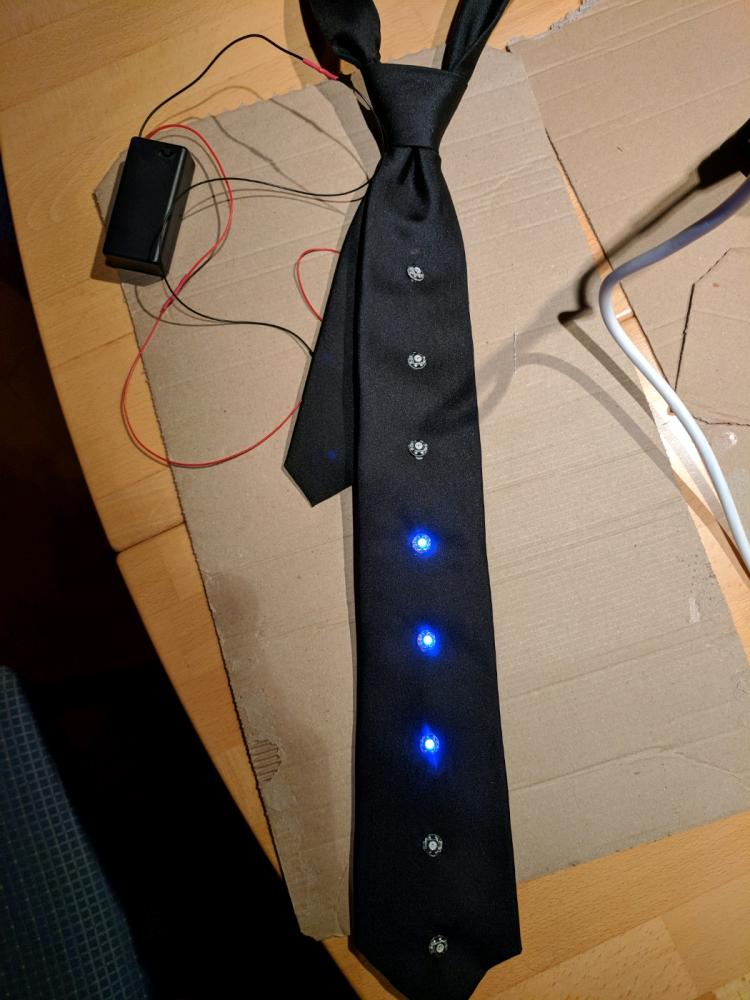 I have made this RGB LED tie. One of my friends and me had the idea at 2 am and now it has come to reality :D ...
 Stress testing my new cnc, say Hello World roundy
Fuck. The entire day to do this shit.
The screen was my first experiment, but because of a bad module (i2c) it didn't worked.
Today I finnaly got it to work.
Starting making everything almost like in the picture, everything mounted (and lots of black hot glue, no wires showing...
Didn't work.
One hour breaking everything apart without damaging the screen... Was a loose wire.
Started again... Didn't work...
The pot is also damaged, sometimes it works, others need to turn it hard.
New pot.
New set of wires.
Soldering everything right, testing all wires so no mistakes this time... But it takes so longgggg... Making everything in modules this time (to reuse without having to sordering again. And finally... It works.
By this time I should have 3 or 4 learning projects finish (I really wanted the screen to adapt all output in text, no serial, no blinking less, everything in modules, code prepared so, when I get my 40+ packages from China I already have a prototype tester ready.
10 hours... Fuck I'm really addicted, or else I would just solder everything together :D
rant
lcd
arduino