
Ranter

Join devRant
Do all the things like
++ or -- rants, post your own rants, comment on others' rants and build your customized dev avatar
Sign Up
Pipeless API

From the creators of devRant, Pipeless lets you power real-time personalized recommendations and activity feeds using a simple API
Learn More
Comments
-
WOW... you should trip the tips to decrease the chance of short circuit... :D Looks like mine.
Now this L293D thing with power is worring me... and can't find the info I want... should the L293D get power from the arduino to steep the motor? -
 mk3d34837yEverywhere people says to split the controller and motors alimentation. But why.. i think when motor start, that create a current peak.
 -
@mk3d Because if the chip or motor draws more than the MCU can suply it can fry it...
That's what I'm afraid off...
As it's weird... I don't think the h-bridge should power the stepper also... -
Check your wiring, make sure to have a good common ground.
An a 2 different power lines for logic and motors.
Otherwise
Your motor will burn the mcu's voltage regulator -
@shelladdicted That's what I'm afraid off... It wasn't supposed to run on the MCU power...
But the board is such a mess I can't really see any bad connections...
Tested every connection with a multimeter and they looked ok... -
I added a 5v-12v In for the L293D power,
And connected Arduino 5V to L293DVCC, connected Enable 1 to Enable 2 and VCC...
All grounds are connected...
And both drivers are working with only the MCU power... -
@GyroGearloose find a way to make sure that battery is connected (aka use an ADC and a voltage divider) and stop the motors if battery is not connected. (Check if mcu's voltage regulator heats up too quickly)
And hope that flyback diodes will handle backward noise -
Been checking with a multimiter with the buzzer.
Got a resistance between 800 and 1000 between positive connections
and 600 between the 12V+ and the 5V+ ...
Is this good? -
I really can't find the leak... I mean, it's ok since it's just for testing, but was gonna use it later on a CNC or plotter... It's weird, I can't find anything regarding powering the L293D with only the Arduino... All the tutorials use external batteries, which is good, you don't want to teach bad habits, but man... I know that the ULN2003A will pass the energy from the MCU and add it to the external source, but I don't think an H-bridge should do that...
BTW I'm writing for myself, you guys are my Ducky Friends -
 codex6532367yEE (embedded dev too) here! I looked at the data sheet for the part and the internal circuit diagram makes it look like the two power rails VCC1 and VCC2 are physically isolated. You MAY be getting some slight leakage depending on how they have things configured in silicon, but I doubt it. My best guess is you wired something incorrectly, which isn't hard to do on a perfboard. I would double check that first. Also, don't put much stock in your resistance measurements. For reasons too long to go into, probing in-circuit like that is going to give you a false impression about what is going on. There are too many active devices and other elements that screw with the reading.
Edit: Do you have the full schematic you are using to build the thing?
Edit2: Are you able to take the chip out of the board and measure the resistance between VCC1 & VCC2? You may have accidentally blown something up internally. Static electricity could have even done that. -
@codex653 Hey, yes I already posted the schematic for the L293D, check above.
I know I did everything right, I've been working a lot with these drivers and know them by memory.
It's so hard to small then stuff is so close together... This is the third board with a bridge somewhere.
At least this one won't go to trash, I can still use it to test, but I was gonna replace my CNC drivers with these board...
Well, Start again.
(This is like my project that I must perfect... not all that important but I'm using it to learn how to solder and fix stuff).
Still, for tests, this is workable...
Edit. Oh full sketch not yet, but I can do it... Gonna do a tutorial for this so it's just what I will eventually have to do.
Edit2: Yes I do, I did it with rails specifically to exchange the chip... and since I reuse the chips would be possible, but like, 2 chips have the strange same behavior... -
Ok, I was talking to my brother, a fucking electronics engineer, who doesn't even have the time to take his eyes from the TV for 2 minutes, when I got the solution myself...
Well, isn't a solution, I'll try and try again until I do this board perfectly, but to save this board I'll just use a power bank to power the 5V (taking the 5V out of Arduino), and just leave a GND to the arduino. Cheap Hack, but If I burn something it's the chips, not my duino. -
Problem solved... Well not solved, this board is still shit, but problem solved. lol
I have to make a new one because I can't just desolder everything to redo it...
On the plus side, I already have enough material to build my third CNC... (With my second still waiting for the steppers lol) -
 Condor315487yYou don't want to power the motor from the Arduino (I suspect it's that if even when the 12V line gets disconnected, the motor keeps turning). Use a separate voltage source for the motor, for both VCC and ground (in case it's floating and to prevent excessive ground current into the Arduino). Only the signal wires (enable and so forth) should come from the Arduino. Perhaps you can power the motor controller from the Arduino as well. But you don't want to introduce the 5V into the motor. VSS is for powering the controller I think, you can introduce that from the Arduino. But the VCC on the motor controller is for the motor. You should connect only the 12V line from another supply there. Not sure where the ground of the motor driver itself goes to though? Perhaps it's sharing the ground with both the Arduino's 5V and the separate 12V line.
 -
@Condor Yep, both lines are separated, only the GND is common. The weird is that if I only provide power from the Arduino the motor spins, So, I'm thinking somehow the 5V from the Arduino are passing current to the VCC line... Although I can't figure out where...
I'll build the same circuit today in a breadboard to see what happens... If the problem is the soldering I can add an extra 5V battery for the controller, separating the VSS from the Arduino... If something burns it is the driver, not the Arduino.


Related Rants

 One of my personal projects.
Just trying something new ☺
One of my personal projects.
Just trying something new ☺
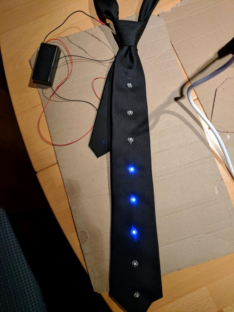 I have made this RGB LED tie. One of my friends and me had the idea at 2 am and now it has come to reality :D ...
 Stress testing my new cnc, say Hello World roundy
!rant
Four hours of work.
You think you write spaghetti code? I write spaghetti wires.
H-Bridge dual motor tester for stepper motors.
Speed is controled by pot.
H-bride are L293D.
My third board, and the first that won't go to the trash.
Question. With the baterry off the motor continues spinning with the 5v from arduino.
My question is, is the L293D suposed to do that? Or do I have a short circuit somewhere that is giving power to the motor? Meaning it can burn the arduino.
Runs a 12v stepper from a CD-Rom driver perfectly at 5v from the arduino and actually starts to act strange when I turn the 12v on. (maby the circuit it's adding 12v + 5v?)
rant
arduino
diy eletrónics
l293d
stepper motors
cnc