
Ranter

Join devRant
Do all the things like
++ or -- rants, post your own rants, comment on others' rants and build your customized dev avatar
Sign Up
Pipeless API

From the creators of devRant, Pipeless lets you power real-time personalized recommendations and activity feeds using a simple API
Learn More
Comments
-
@Demolishun 1. I created this logic.
2 Exactly. For left shifts, I use the n+1th component's output for the nth component's input.
For right shifts, I do the opposite of that. I redirect the output of nth component's output to the n+1th component's input. -
Looks like after the intended shift, there's "half" of another shift cycle happening. It's long since, but IIRC, such effects happen when the logic has a loophole with regard to the clock cycle, i.e. that shit happens while the clock flank changes state.
You know, glitches like what happens when you have a Karnaugh map and you cross over between disjoint regions. -
@Fast-Nop I completely forgot about the existence of hazards. Thanks for the reminder! :)
-
@Fast-Nop It turns out the hazard was way deeper than I thought.
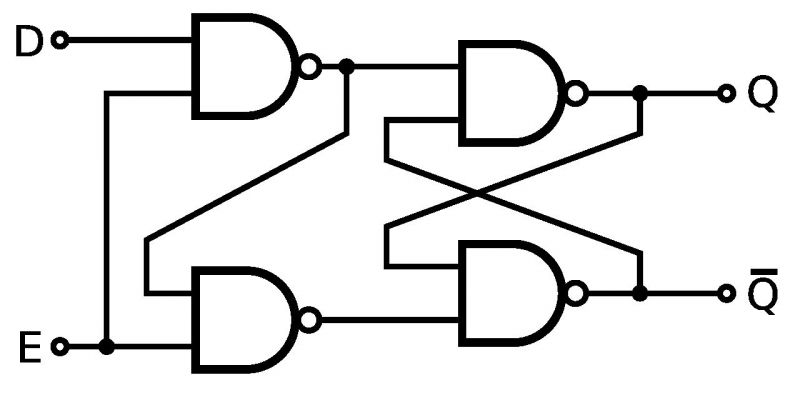
It is in my d flip flop. Apparently, I used a different version of the d flip flop than I had to use. -
You don't have the single NOT component. You redirect the "D NAND Clock" component's output. Thus no delay and therefore no glitch.
-
@-ANGRY-STUDENT- The upside is that you have a defined point within your clock cycle where the data acquisition happens - that is, not at any time where the levels are changing and may cause transient output spikes.
The downside is that you need twice the amount of FFs.
Another downside is that changes will only propagate with each clock cycle so that your shifter chain would need several clock cycles.
However, if your shifter is faster than the clock, then you could wire only the master FFs in the shifter and use the slave FFs as stabilised output stage. -
-
@Haxk20 I just thought maybe if more people were interested you'd make it actually look good. -_-
-
@Haxk20 mate, you sound a little bit too aggressive in the comment sections. Wanna talk about what caused it?
-
@-ANGRY-STUDENT- The easiest way to become a grumpy old man is starting as grumpy young man.


Hey, fellow dRs.
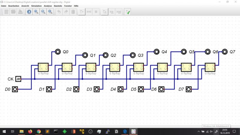
I may need some help regarding this circuit.
It is about an 8 Bit multifunctional shift register with a 2 Bit instruction set.
These work:
If "Sel" is 0x00, the circuit loads data into its 8 D flip flops.
If "Sel" is 0x03, the circuit replaces all data with 0s.
These don't work (they do, but they do it in a very strange way and end up filling 1s instead):
If "Sel" is 0x01, it is supposed to ringshift bitwise to the right.
If "Sel" is 0x02, it is supposed to ringshift to the left.
As mentioned above. They do it in a very strange way. If we have 10000000, it will shift to the left or right depending on the "Sel"'s binary value. Let us say we want to shift it right. The output will turn from 10000000 to 01000000 (which is what we want), BUT after that it adds another 1 to it: 01100000. It keeps doing it until every single Bit is a 1. Same thing happens with the left ringshift.
I will include the other circuits used in this circuit in the comment section.
question