
Ranter
Join devRant
Do all the things like
++ or -- rants, post your own rants, comment on others' rants and build your customized dev avatar
Sign Up
Pipeless API

From the creators of devRant, Pipeless lets you power real-time personalized recommendations and activity feeds using a simple API
Learn More
Comments
-
 Crowns1927y@raldo94 NI Multisim for the schematic and NI Ultiboard for the layout. 🙂
But maybe something like this is helpful for you: https://youtu.be/35YuILUlfGs
@schug Yeah we have the possibility to make our own words by randomly using some words and patch them together. 😄 -
Crowns1927y@raldo94 missed out to say that we ordered via JLCPCB for 2$/10pcs but 21$ for shipping. 😄
-
Crowns1927y@JohnScott yeah that preview image is superb. Was hard to find so small and long resistor!
-
 0xBE5A1327yGlückwunsch! Getting a well deserved good grade after putting in so much hard work is a great feeling. Still waiting on my results from this semester 😅
 -
Crowns1927y@mrgadget @0xBE5A Thank you. 🙂
I hope the the 3 exams we write (2 of them consisting of 2 different lectures - Math + Physics and Electronic Components + Automotive electronics) I'm not the best with electronic components like analog lowpass filters, OPs and calculation of them, so there will be some nightshifts ahead I guess, but all the other presentations were good so far to hopefully get a 1.X in my masters degree. Wish me luck. 😄 -
@WildOrangutan started using circuit maker, but got lost. had not read any documentation or tutorials before
-
 LuxARTS15897y@Crowns I came to make the same question about how did you make the PCB. I thought that you made the PCB it self and not only the design.
Why did you use an Arduino when you can use a STM32 which it's cheaper and more powerful? -
Crowns1927y@LuxARTS we had plenty of the 328p laying around who didn't get used, so we decided to use them.
I own a stm32f429disc just for learning some stuff and have a ST-Link v2 so we would have been able to program a stm32 board, but it was just cheaper for us to use the components we had laying around. 😄 -
LuxARTS15897yIn that case cool! I've got like 30 atmega328 but I decided to move to ARM a few months ago because the compatibility between MCU when using the HAL library it's awesome. Also, less consumption, faster processor and lots of peripherals.
-
Crowns1927y@filthyranter we will continue this project to a finished product. Don't know if we will do more than 10 of them, but we can do another assignment with it which is the main reason for us to do it. I don't know if there is much interest in this product to really sell it, furthermore we would need to know which cars we need to add to the database an the algorithm they use for the blink code. 😀


Related Rants
-
 xjose97x20Just saw a variable in C named like this: long time_ago; //in a galaxy far away I laughed no stop.
 -
 Unskipp24So this happened last night... Gf: my favorite bra is not fitting me anymore Me: get a new one ? Gf: but it ...
 -
 sam966911
 Hats off to this lady .... I would have just flipped the machine
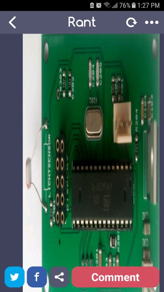
Today we presented our project in Embedded Systems. We made our so called "Blinkdiagnosegerät" (blink diagnosis device) which is used to get error codes from older verhicles which use the check enginge light to output the error. (for reference: http://up.picr.de/7461761jwd.jpg ) This was common for vehicles without OBD.
We made our own PCB, made a small database for 2 vehicles and used a Suzuki Samurai instrument cluster for the presentation (hooked up to an Arduino UNO and a relay for emulating some Error Codes)
Got an 1.0 (A) for the project. Feel proud for the first project done in C++ and making our own PCB. So no rant, just a good day after all the stress in the last weeks doing all assignements and presentations.
Next week we hopefully finish our inverse pendulum in Simulink and then the exams are close. :D
random
blinkdiagnosegerät
atmega328p
c++
soon master of engineering
pcb